
In Ontario, LVL beams are not in the Building Code’s Part 9 span tables, so an engineer sizes the beam, its posts and its footings for your actual loads and shows them on the permit drawings.
An LVL beam and a steel beam can both carry the floor, wall or roof above a new opening in a house. Which one suits your project depends on the span, the loads, the headroom and how the posts and footings take the load down to the foundation. Elmid’s residential structural engineers prepare that design for house renovations and additions in Toronto and across Ontario.
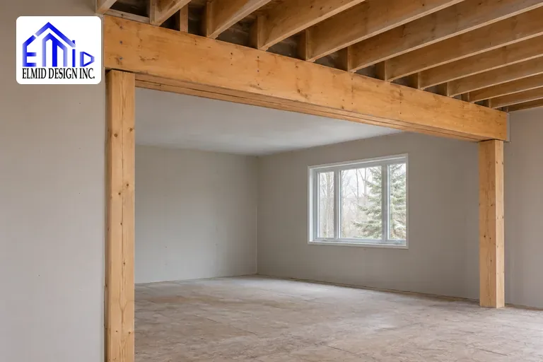
The image at the top of this page is illustrative only. It shows a general example of a new beam over a wide opening, not a real project, and it shows no design values.
Elmid Design Inc. is an engineering consultant. Our structural work is residential only: we size structural members, posts and footings for houses and prepare the permit drawings. A contractor you hire supplies and installs them, and the municipality reviews the permit and inspects the work.
What is the difference between an LVL beam and a steel beam?
LVL (laminated veneer lumber) is an engineered wood product made of thin wood veneers glued under heat and pressure, usually installed as two or more plies fastened together. A steel beam in a house is usually a hot-rolled W-shape. Steel generally carries more load for the same depth; LVL is lighter and is framed like wood.
LVL is sold in standard depths and in plies about 45 mm (1¾ in.) thick. Manufacturers label it with a stiffness rating, for example 2.0E, and publish design values for their own product. Two LVL beams of the same size from different manufacturers are not automatically interchangeable, which is why the drawings name the product or the design values it must meet.
A steel W-shape is named by its nominal depth and mass. A W200×27, for example, is about 200 mm deep and weighs about 27 kg per metre. Steel beams in houses usually sit on steel or wood posts with bearing plates, and a wood nailer is often bolted to the top flange so the floor joists can be fastened to it.
Two other options appear in house work. A flitch beam is a steel plate bolted between wood members. A glued-laminated (glulam) beam is made from layers of dimension lumber. Both are also designed for the loads they carry.
Where do LVL and steel beams show up in house renovations?
Most often where a load-bearing wall is removed or widened for an open kitchen, where a basement post is taken out to lengthen a span, where an addition or second storey adds load to an existing beam, and over wide garage or patio-door openings. Each case changes the loads, so each needs its own check.
- Open-concept renovation: a bearing wall between the kitchen and living room is replaced by a beam, often flush with the ceiling.
- Basement: an existing steel or wood beam is kept, but a post is removed, so the span roughly doubles and the beam usually has to be replaced or reinforced.
- Addition or second storey: new floors or roof bear on an existing beam that was sized for less load.
- Wide openings: garage doors, patio doors and window walls need headers or beams sized for the wall, floor and roof above.
Our guide to load-bearing wall removal in Ontario covers how to tell whether a wall is bearing and what the permit asks for.
When does a beam need an engineer in Ontario?
The 2024 Building Code (O. Reg. 163/24, in force January 1, 2025) has Part 9 span tables for built-up wood and glued-laminated floor beams and for some steel floor beams. LVL is not in those tables. A beam outside the tables, or with loads or supports the tables do not cover, needs engineering design.
Two articles of Division B set the prescriptive limits: Article 9.23.4.2 (spans for joists, rafters and beams, including built-up and glued-laminated wood floor beams) and Article 9.23.4.3 (steel floor beams with a laterally supported top flange). Part 9 also allows structural members to be designed under Part 4 instead, which brings in CSA O86 for wood, including LVL, and CSA S16 for steel.
In practice, renovation beams leave the tables often: a point load from a post or wall above, a roof load, a beam that is continuous over a post, or an existing footing of unknown size. Additions that put new loads on an existing beam fall in the same group. The municipality decides what it needs to see; confirm with its building department.
Who sizes the beam for a building permit?
For most house renovations, a Professional Engineer works out the loads from the roof, floors and walls above, selects the beam and designs the posts, connections and footings. Some lumber suppliers run the manufacturer’s software for a single LVL member, but that sheet covers the beam only, not the full load path the permit drawings must show.
The roles are worth keeping separate:
- Owner: applies for the permit, or authorizes an agent to apply.
- Designer: a designer with a BCIN (Building Code Identification Number), an architect or the owner, where exempt, prepares the house drawings.
- Engineer: designs the structural members that fall outside the Part 9 tables and prepares that part of the drawings.
- Contractor: supplies, shores and installs the beam to the approved drawings.
- Municipality: reviews the application and inspects the work.
The plans examiner checks whether the drawings show a complete path for the load from the roof down to the foundation. Elmid prepares the structural part of the building permit drawings and answers the examiner’s comments on its own drawings. Roof trusses are separate: the truss manufacturer’s engineer designs them, and Elmid reviews the truss shop drawings against the building design.
How does an engineer size a residential beam?
The engineer traces the load path from the roof to the foundation, adds up the loads on the beam, and checks bending, shear, deflection and bearing for the span and support conditions. Then the posts, connections and footings are checked for the same loads, because a beam is only as strong as what holds it up.
- Trace the load path: what sits above the beam, including floors, walls, the roof and any post bringing a load down from higher up.
- Add up the loads: the weight of the building itself, the floor live loads in the Building Code, and snow loads from the Code’s climatic data for the municipality (Supplementary Standard SB-1).
- Check the member: bending and shear strength, deflection limits so the ceiling and floor above do not crack or sag, and bearing length at each end.
- Check stability: for steel, whether the top flange is laterally supported by the joists; for LVL, how the plies are fastened together.
- Check the supports: post size and buckling, the connection at the top and bottom of each post, and the footing size for the soil.
The result is a member size with its supports and connections, written on the drawings so the contractor and the inspector see the same information.
What do the permit drawings show for a new beam?
The drawings show the beam size and material (LVL grade and number of plies, or the steel section), where it bears, the posts or columns at each end, the connections, and the footings under the posts. They also note the loads it carries and that the contractor provides temporary shoring while the work is done.
- Member: LVL depth, width, grade and number of plies with the fastening pattern, or the steel section and its bearing plates.
- Supports: bearing length at each end, post or column size, and how the post is held at the top and bottom.
- Connections: joist hangers, bolts or a wood nailer on a steel flange so the floor joists can be fastened.
- Foundation: new or existing footing size under each post, checked against the load.
- Notes: design loads, temporary shoring by the contractor, and the municipal inspections that apply.
Why not use an online LVL span chart?
Span charts and calculators assume simple, uniform loads on a single span. A renovation beam often carries point loads from a post, a bearing wall or the roof above, and sits on existing posts and footings of unknown size. Those cases need the real loads checked, so a chart answer can be wrong in an unsafe direction.
Manufacturers’ tables are written for their own product and for the load cases printed with them. They are useful for a first idea of depth, but they do not check the post, the connection or the footing, and they do not tell the examiner how the load reaches the foundation.
What about the posts and footings under the beam?
A beam sends its load to its ends. Each end needs a post or bearing wall able to carry it, and the load has to continue down to a footing sized for the soil. In a basement, the existing footing under a new post often has to be checked or enlarged, and that check is part of the design.
On upper floors, the post at each end of a beam has to land on something that can carry it: another post, a bearing wall or a beam below, all the way to the basement. Where the post lands on a floor with nothing under it, the floor framing needs blocking or a new support, and that is shown on the drawings too.
In older houses, basement footings were often sized for the original post spacing and loads, and their size is not always known. When a renovation moves a post or adds load to it, the engineer may ask the contractor to expose the footing so its size can be confirmed, or may show a new footing on the drawings.
How do you choose between LVL and steel?
The choice comes down to span, load, headroom, access and connections. LVL is often used for moderate spans where the plies can be carried in and assembled on site. Steel is often used for longer spans, heavy point loads, or where a shallower or flush beam keeps headroom. The engineer compares both for your actual loads.
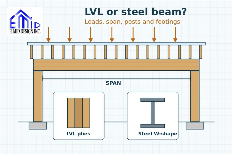
| Item | LVL | Steel |
|---|---|---|
| Material | Engineered wood veneers glued into plies | Hot-rolled steel section (usually a W-shape) |
| Depth for a given load | Usually deeper | Usually shallower |
| Getting it into the house | Plies carried in one at a time and fastened together | One heavy piece; access and lifting need planning by the contractor |
| Connecting the joists | Joist hangers or bearing on top | Bearing on the flange or a bolted wood nailer |
| Design standard | CSA O86 or the manufacturer’s evaluated design data | CSA S16 |
| Who sizes it | The engineer, with the posts, connections and footings | The engineer, with the posts, connections and footings |
A flush beam sits within the ceiling depth, so the room has a flat ceiling, and the joists hang from it on hangers or a ledger. A dropped beam hangs below the ceiling, which is simpler to connect but lowers the headroom under it. Headroom is often what decides between LVL and steel in a basement.
What happens on site when the beam goes in?
The contractor builds temporary shoring to carry the floor or roof while the wall is removed, installs the beam, posts and footings to the approved drawings, and calls for the municipal inspections. If a different beam is proposed on site, the change goes back to the engineer and, where needed, to the municipality before it is used.
Where the municipality requires the design engineer to review a stage of construction, Elmid can carry out that review for its own design. Elmid does not supervise construction or install anything; the contractor is responsible for the work and for site safety.
How much does an engineered beam design cost?
Costs depend on the site and scope: the span, what the beam carries, how many posts and footings are affected and what the municipality asks for. Elmid prepares a written proposal after reviewing photos and any existing drawings, and offers a free consultation and a free quote. Elmid designs the beam; a contractor supplies and installs it.
What should I send before the beam is designed?
Send photos of the wall to be removed or opened, the floors and roof above it and the basement below, any existing drawings or a survey, and a sketch of the opening you want. Note what sits above the wall, such as a bearing wall, a bathroom or a roof ridge, because those loads decide the size.
- Photos of the wall, the ceiling and floor framing where visible, and the basement under it.
- Existing drawings, if you have them, or measurements of the rooms involved.
- The opening you want: width, ceiling height, flush or dropped beam.
- Whether the roof above is framed with trusses or rafters.
- The municipality and the address of the house, so the right climatic data and local requirements are used.
Elmid prepares the design and drawings within an agreed scope. You or your contractor submit the permit application, the contractor builds the work, and the municipality carries out its inspections. See our building permit drawing services or contact us for a free consultation.
Areas we serve
Elmid Design Inc. prepares residential structural design and building permit drawings in Toronto and across the Greater Toronto Area, including York, Peel, Halton and Durham regions, and in other Ontario municipalities, depending on project scope and availability. Contact us to discuss your project.
Related articles
- Load-bearing wall removal in Ontario
- Additions permit drawings in Ontario
- Engineered truss drawings for a Toronto building permit
Sources
- Government of Ontario, Ontario’s Building Code (2024 Building Code, in force January 1, 2025), accessed November 21, 2026.
- O. Reg. 163/24, Building Code, e-Laws, accessed November 21, 2026. Division B, Article 9.4.1.1 (structural members conform to Part 9 or are designed by good engineering practice or under Part 4; climatic data from SB-1), Article 9.23.4.2 (spans for joists, rafters and beams) and Article 9.23.4.3 (steel beams); Supplementary Standard SB-1 (climatic data). Article numbers checked against the 2024 Building Code Compendium, Part 9, ontario.ca, November 22, 2026.
- CSA O86, Engineering design in wood; CSA S16, Design of steel structures (referenced by Part 4 of the Building Code).