
Watermain Layout: Looped vs Dead End in Ontario
A watermain layout comparison examines looped and dead-end connections, operating states and development phases. Understand the network before treating a drawn loop as proof of capacity.
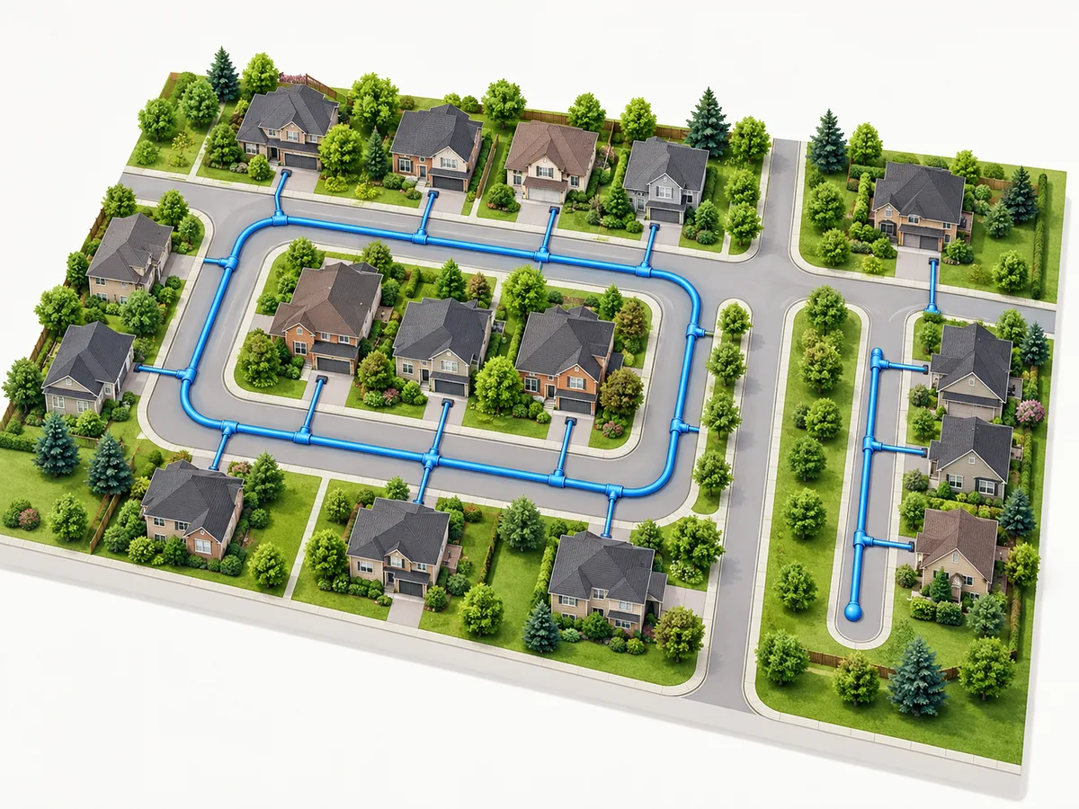
A looped vs dead end watermain comparison starts with the routes that water can take through a network. A loop provides a connected path around part of the system. A dead-end main terminates without a continuing connection. However, neither label proves that a proposed development has adequate pressure, fire flow or acceptable water quality.
For an Ontario project, the useful question is how the proposed arrangement works in its actual setting. Review the available connections, operating conditions, development stages and authority requirements together. Elmid Design Inc. provides site servicing engineering and design support to help coordinate those questions with the development concept.
Watermain layout: the short answer
A connected loop can offer a different route around an isolated segment. That benefit depends on the real connections and valve arrangement, not simply a ring drawn on a plan.
A dead-end arrangement needs particular attention to its terminal condition and operating provisions. A future connection does not make today’s unconnected main a functioning loop.
Compare the layouts using the same development assumptions. Keep capacity assessment, ownership and permission to connect as separate questions.
What does a looped watermain mean?
A looped watermain connects back into the network rather than ending at its last branch. In a simple diagram, two routes can reach a portion of the development. Larger systems may contain several linked loops rather than one neat ring.
The drawing should show where each route connects and which segments form the loop. It should also distinguish existing infrastructure from proposed work. Otherwise, a reader may assume that a connection already exists when it depends on a future project.
A loop describes connectivity. It does not describe every feature of the upstream supply. Two routes could still share an upstream constraint, so the engineer needs to trace the wider arrangement before describing the benefit.
Water distribution layout: grid, loop and tree
A grid contains interconnected routes. An arterial-loop arrangement organizes connections around major routes. A tree branches outward and may finish in several dead ends. Real networks often combine these patterns because streets, property boundaries and earlier development shape their layout.
For an owner, the terminology matters less than a readable diagram. Ask the designer to identify the connected paths, terminating branches and proposed tie-ins. This makes the comparison understandable without pretending that every system fits a single pattern.
Also define the area under discussion. A neighbourhood may have a connected distribution network while a short branch within it remains dead-ended. Calling the whole area looped should not hide the branch that needs separate attention.
What is a dead-end watermain?
A dead-end watermain has a terminal point rather than a continuing connection through the network. It may serve a completed area or form an interim arrangement before later works connect it elsewhere. Those situations raise different questions for the water distribution layout.
A temporary label alone does not resolve the interim condition. The proposal needs to describe what will operate before the later connection exists. It should identify the responsible parties and the evidence needed for that stage.
Do not confuse every service pipe to a building with the distribution-layout question. The classification and applicable requirements depend on the actual system. Establish that context before applying a municipal watermain concept to a private site.
Permanent and interim dead ends
For a permanent dead end, the discussion concerns the intended long-term arrangement. For an interim dead end, it also concerns the changeover to the ultimate network. Keep both states visible in the submission.
A proposed connection across neighbouring land, for example, may depend on an agreement and another development’s programme. Until those matters are established, the current phase cannot rely on a line labelled future loop as though it were available.
Record what would trigger the connection and what happens if it is delayed. This turns an optimistic phasing note into a question the project team can resolve.
Looped vs dead end watermain: compare the same conditions
| Question | Looped arrangement | Dead-end arrangement |
|---|---|---|
| Connectivity | Trace the connected routes and their shared constraints. | Identify the terminal point and the route serving it. |
| Isolation | Check which route remains available in the proposed isolation scenario. | Check which users depend on the segment under review. |
| Operations | Coordinate the layout with the operator’s requirements. | Resolve terminal operating provisions with the responsible operator. |
| Phasing | Confirm when every connection needed for the loop becomes available. | Define the interim or permanent condition explicitly. |
| Performance | Assess the relevant demands and network conditions. | Assess the same demands and network conditions. |
This comparison is a framework for questions, not a design selection table. Neither column supplies pipe sizes or proves acceptance. The authority and project-specific engineering assessment establish the applicable requirements.
Use the same development description when comparing alternatives. A loop serving the completed development and a dead end serving only its first building are not equivalent cases. Separate differences in layout from differences in demand and construction stage.
What Ontario guidance says about watermain looping
Ontario’s drinking-water design guidelines describe loop, grid and tree configurations. Section 10.3.1 favours practical tie-ins or looping to reduce dead ends, improve reliability and address stagnation concerns. Where dead ends cannot be avoided, it calls for adequate flushing provisions. The chapter also notes that local or regional requirements may be more stringent. Read the Ontario distribution-system design guidance.
Separately, Ontario’s Watermain Design Criteria concern specified future alterations authorized through a drinking water works permit for municipal residential systems. Sections 5 and 10 address unavoidable dead ends and flushing provisions. This is a defined permit context, not a blanket approval rule for every private pipe. See the Watermain Design Criteria and their stated application.
For the project team, the next step is to confirm which documents govern the proposed works. Record the system owner, reviewing authority and applicable submission requirements. Resolve uncertainty about the approval route before treating a general guidance statement as the complete design brief.
Avoid turning guidance into an automatic verdict
“Loops are preferable” and “this loop is acceptable” are different statements. The first describes a general direction. The second requires evidence about the proposed arrangement and its setting.
Likewise, acknowledging that unavoidable dead ends need attention does not establish that a particular dead end will receive approval. A design discussion should explain the constraints and the proposed response, without replacing the authority’s review with a broad quotation.
Keep applicable requirements in a project-specific design basis. If a municipal reviewer gives direction, retain its date and context. A comment from another property may help identify a question, but it should not become this project’s approval evidence.
Trace the watermain layout before claiming redundancy
Start at the proposed connection points and follow the routes beyond the site boundary. Ask what infrastructure the two paths share. A diagram that stops at the property line can conceal a common upstream dependency.
Next, identify the operating state assumed in the comparison. A physical connection may not function as an available route in every operating condition. The engineer and system owner need compatible information about that arrangement.
Finally, state the particular benefit being evaluated. An alternative path around one segment is a narrower claim than uninterrupted supply under any event. Use language that matches the scenario actually assessed.
Watermain looping and segment isolation
An isolation review considers what remains connected when a defined segment is unavailable. At concept stage, a diagram can help identify the users and routes involved. Detailed conclusions still need the appropriate engineering and operator input.
Ask which segment the review removes, which connections remain available and which users depend on them. These questions make the assumptions visible. They also show whether the preferred layout relies on equipment or works outside the project scope.
This is a design coordination exercise, not an instruction to operate valves. Property owners should not test a concept by changing public-system equipment. The responsible system operator controls operational work.
Keep watermain layout separate from capacity
A connected route does not create unlimited upstream supply. Capacity assessment considers the proposed demands and relevant network conditions. Layout can affect that assessment, but the two questions should remain distinguishable in the report.
For example, a concept may establish a feasible corridor for a second connection while leaving the receiving system’s performance unresolved. The drawing can show the corridor without describing the development as fully serviced.
Similarly, an available pressure observation does not answer every future operating case. State what information supports the conclusion and what further analysis remains necessary. Avoid using a layout label as a shortcut around the capacity work.
Domestic demand and fire-protection questions
The development team needs a consistent description of the proposed uses. Domestic demand and fire-protection information should come from the appropriate project inputs. A change in building use or scale can affect the assessment even when the pipe route stays the same.
Coordinate the civil and building-services assumptions before presenting a conclusion. The civil drawing, supporting analysis and building information should describe the same proposal. Where another specialist supplies an input, identify that responsibility rather than silently selecting a value.
This article does not provide fire-flow requirements or a pipe-sizing method. Those decisions require the applicable criteria and project-specific assessment.
Review watermain layout and operating conditions
A useful concept discussion asks how the proposed area will actually be occupied and used. Give the designer a realistic programme rather than only the final site plan:
- Compare occupancy stages. A fully occupied development and an early phase with few users can present different conditions.
- Identify variations in use. Record seasonal uses, delayed occupancies and areas that may remain inactive.
- Separate facts from assumptions. A planned opening date may change; do not describe an uncertain programme as a verified operating condition.
These are inputs for review, not reasons for an owner to select an operating procedure. The responsible professionals and operator determine what the information means for the system.
Dead-end watermain design and operator coordination
Discuss terminal arrangements with the responsible authority and operator while the layout can still change. Their input may affect space, access, equipment locations and the supporting submission. Leaving this discussion until the final drawing can create avoidable redesign.
Show where the proposed terminal arrangement sits relative to roads, property boundaries and other features. Identify who would own and access the relevant infrastructure. A technically described device is not a complete solution if the operational responsibility remains unclear.
Do not prescribe a universal flushing frequency from a general article. The operating programme depends on the actual system and the responsible operator’s requirements. Nor should a homeowner manipulate hydrants or valves to investigate a concern.
Watermain looping across development phases
A phased project needs a separate picture of each meaningful network state. The ultimate drawing may show a complete loop while the first phase operates without one. The servicing narrative should explain that difference clearly.
Identify the works each phase needs before it can rely on its proposed arrangement. Distinguish infrastructure within the owner’s control from external dependencies. A future municipal project or neighbouring connection needs appropriate confirmation.
Then show how the interim arrangement changes. The drawing and report should identify the connection that completes the loop and the assumptions supporting its availability. Avoid presenting an aspirational date as a confirmed dependency release.
Watermain layout when a second connection is delayed
Ask what happens if the later connection arrives after the proposed occupancy. The answer may require further assessment, a revised sequence or a different concept. It should not disappear behind a note stating that the loop will eventually close.
Keep the issue in the decision record until the responsible parties resolve it. Record the information needed and the effect on the current proposal. This helps an owner understand whether the uncertainty affects layout selection, timing or the scope of further work.
A development programme can change several times. Review the servicing assumptions when it does, especially if the change alters the duration or extent of an interim condition.
Build evidence for a watermain layout comparison
Start with current base information and the latest development concept. Add available network records, previous reports and written authority comments. Keep source dates visible so the designer can identify gaps or conflicting information.
Ask for an explicit connection schedule. Each proposed tie-in should have a location, status and information source. A point on a concept plan may represent an existing main, a proposed extension or an unconfirmed opportunity; those are not interchangeable.
Include the intended development stages and relevant building-service inputs. If alternatives remain under consideration, explain them. The engineer can then compare defined options rather than assume that one preliminary layout is fixed.
| Evidence | Question it helps resolve |
|---|---|
| Current network records | What connections and segments are known? |
| Site concept and survey | Where could the proposed routes fit? |
| Development and occupancy programme | Which network state serves each stage? |
| Authority and operator direction | Which requirements and responsibilities apply? |
| Supporting engineering assessment | What performance conclusions does the evidence support? |
Label uncertainty instead of hiding it
Separate confirmed records, design assumptions and unresolved questions. This allows the team to progress useful work without suggesting that every input has equal reliability. It also makes review comments easier to assign.
For example, an old record may establish that a main was proposed, but not its current condition or operating status. The next task is to identify the confirmation needed. Drawing the old line more neatly does not improve the evidence behind it.
Keep uncertainty tied to its consequence. Explain whether an unresolved connection prevents selecting a layout or simply requires confirmation before a later design stage.
Compare watermain layout, land access and design interfaces
A loop needs a feasible route as well as a useful connection. Check its relationship with buildings, roads, utilities, landscape areas and property limits. The servicing concept should reflect the coordinated site arrangement.
If a route crosses land outside the applicant’s control, flag that dependency early. Engineering drawings do not grant land rights. The owner and appropriate advisers need to resolve access and agreements through the relevant process.
Coordinate the watermain route with other civil systems without turning the comparison into a general servicing report. The focused question is whether the proposed connection paths can fit and function within the agreed development concept.
Make the preferred watermain layout traceable
Record why the preferred watermain layout offers an advantage over the alternatives. Identify the confirmed tie-in, any unresolved corridor and the assessment needed before detailed design. This gives later designers a reasoned choice, not an unexplained “preferred loop” label.
Review the water distribution layout before submission
Read the concept as someone who has not attended the design meetings. Can you identify the existing connections, proposed loop and terminal branches without an explanation? A useful legend and consistent line types help the reviewer follow the intended network.
Check that the report names the same connection points as the drawing. If a tie-in moved during coordination, update the narrative and any affected assessment. A revised line on the plan does not automatically revise the assumptions in a separate report.
Then compare the phase drawings with the programme. The first occupied area should appear in the network state that would actually serve it. Keep future works visually distinct, even when they form an important part of the preferred ultimate arrangement.
Match watermain layout conclusions to the evidence
A feasible corridor is not a confirmed connection. State which conclusion the evidence supports without presenting an unresolved watermain layout as a completed servicing solution.
Ask whether the stated benefit follows from the assessed scenario. If the review considered a local segment isolation, it should not imply protection against every upstream interruption. Precise language helps the owner understand what the engineering work actually supports.
Likewise, distinguish proposed operating provisions from an accepted arrangement. Identify any operator consultation still needed, particularly for terminal flushing provisions.
Respond to watermain layout comments with a change record
When a reviewer asks about watermain looping, identify the underlying question. It may concern an available route, an interim condition or a missing explanation. Respond to that question rather than adding a generic paragraph about the benefits of loops.
- Identify the evidence. Link the response to a drawing revision or supporting assessment. If the design has not changed, explain which existing information answers the concern.
- Keep open issues visible. Identify missing information instead of marking the comment resolved prematurely.
- Review affected alternatives. A changed connection assumption may affect more than one layout. Check the consequences before carrying the original conclusion into the next submission.
- Coordinate the revised package. Share relevant changes with the project team because a revised connection can affect site planning and other civil drawings.
Illustrative watermain layout examples: loops and dead ends
The following scenarios are hypothetical teaching examples. They are not Elmid Design Inc. project records, approved designs or predictions of a municipality’s decision. Their purpose is to show how different evidence can change the question.
Example one: two routes share an upstream constraint
Imagine a proposed development with connections at two nearby locations. Its concept drawing shows a loop around the buildings. The owner initially describes the arrangement as two independent supplies.
The design team traces both routes beyond the property. They lead back to a common upstream segment. This does not make the loop meaningless, but it limits what the drawing alone can demonstrate.
The next step is to define the scenarios that need assessment. One may concern isolation of a local segment; another may concern the shared upstream condition. Keeping those questions separate avoids promising a benefit that has not been established.
The decision record would describe the connected layout, the shared dependency and the remaining assessment. It would not announce guaranteed continuity simply because two tie-ins appear on the site plan.
Example two: the future loop is outside the first phase
Consider a development whose ultimate drawing connects through a later parcel. The first phase could reach an existing main, but the second connection depends on future works outside the initial construction area.
The owner wants to advance the first building before those later works. Consequently, the engineer needs to distinguish the first-phase watermain layout from the completed network. Calling the project looped describes only the ultimate concept.
The team identifies the interim terminal condition and seeks the relevant authority and operator input. It also records who controls the future connection and what evidence would establish its availability.
If the timing remains uncertain, the owner has a real decision to make about further assessment or sequencing. The useful outcome is a clear dependency, not a promise that a future connection will solve every present concern.
Example three: the shorter route hides a coordination issue
Suppose two concept routes could complete a loop. One is shorter on the plan but crosses a constrained shared corridor. The other follows a longer route within an area the project can coordinate more directly.
The comparison should identify those differences without selecting a winner from length alone. Ask what information each alternative needs, which parties control the route and how the proposal interfaces with other services.
Cost and programme discussions can follow a defined concept. They should not rely on a universal price per metre or assume that the shortest line has the fewest dependencies.
How Elmid Design Inc. supports water servicing decisions
Elmid Design Inc. prepares site servicing drawings and supporting engineering analysis. The agreed assignment can coordinate water connections with the development concept, related civil drawings and available authority information. The scope should identify the particular questions the work will address.
For a network-layout comparison, useful deliverables may include a clearly labelled concept, an alternatives discussion and a record of unresolved dependencies. Additional capacity work or specialist inputs need an explicit scope rather than an assumption that a layout drawing includes everything.
Elmid Design Inc. provides engineering and design consulting, not watermain supply or installation. Municipal and operator decisions remain with the responsible parties. Review the firm’s site servicing engineering services for the broader design scope.
What to send for a watermain layout discussion
Provide the property location, municipality, current site plan and intended development stages. Include available servicing records and the complete authority comments, not only the sentence mentioning a loop.
Explain the decision you need to make. Perhaps the issue is a possible second connection, an interim dead end or a change to the development sequence. A focused question helps establish the investigation and design work required.
Also identify other consultants and any previous servicing assessment. Reusing relevant evidence avoids unnecessary duplication while keeping responsibility for current assumptions clear.
Frequently asked questions
Is a looped watermain always acceptable?
No. A loop describes connectivity, not automatic acceptance. The proposal still needs the applicable engineering assessment, authority review and connection permissions. Confirm the actual network conditions rather than relying on the label.
Does a dead-end watermain always require replacement?
A general comparison cannot establish that conclusion. The responsible professionals and authority need to review the actual system, proposed change and applicable requirements. Avoid treating an educational article as a direction to alter existing infrastructure.
Does watermain looping prove adequate fire flow?
No. Fire-protection performance requires the appropriate project inputs and assessment. A second route may be relevant, but a drawing alone does not establish available flow or pressure under the required conditions.
Can a future connection count as a working loop?
Not while it remains unavailable. Describe the current or interim arrangement separately from the ultimate concept. Identify the works and confirmations needed before the project can rely on the later connection.
Who decides the flushing arrangement?
The design must coordinate with the responsible authority and system operator. Requirements depend on the actual system and applicable criteria. Owners should not choose a universal frequency or operate system equipment based on a general article.
Is a private service pipe the same as a municipal watermain?
Do not assume the same classification or approval route. Establish ownership, system context and the proposed works first. This article compares distribution layouts; it does not determine the regulatory classification of a particular pipe.
What is the first useful step in a layout comparison?
Put both alternatives on the same current base plan and identify their actual connection points. Then record the network information, operating assumptions and phase dependencies that need confirmation. That gives the engineer a defined question to assess.
Geographic Locations That We Service:
Elmid Design Inc. provides site servicing engineering and design consulting across Ontario service areas. The agreed scope depends on the proposed work, available evidence and applicable review requirements.
We provide engineering services across a wide range of municipalities, each with its own requirements and review processes.
Toronto and Surrounding Areas
We provide engineering services in Toronto and provide grading engineering resources through our Toronto grading plan page.
Our service area also includes Oshawa, Pickering with our Pickering grading plan resources, and Clarington.
Our engineering services also cover Ajax through our Ajax grading plan resources, Whitby, Brock, Scugog, and Uxbridge, including our Uxbridge grading plan resources.
Halton Region
Within Halton Region, we provide engineering services in Burlington, including projects requiring Burlington grading plans.
Our engineering services also cover Halton Hills, supported by our Halton Hills grading plan resources.
Our service area also includes Milton and Oakville, including our Oakville grading plan resources.
Peel Region
Within Peel Region, we provide engineering services in Brampton, including projects requiring Brampton grading plans.
Our engineering services also cover Mississauga through our Mississauga grading plan resources and Caledon through our Caledon grading plan resources.
York Region
Within York Region, we provide engineering services in Vaughan and provide information about Vaughan grading plans.
Our engineering services also cover Aurora through our Aurora grading plan resources and East Gwillimbury through our East Gwillimbury grading plan resources.
Additional service areas include Georgina with our Georgina grading plan resources, Markham with our Markham grading plan resources, and Newmarket with our Newmarket grading plan resources.
Our engineering services also cover Richmond Hill with our Richmond Hill grading plan resources, Whitchurch-Stouffville through our Whitchurch-Stouffville grading plan resources, and King through our King grading plan resources.
Our service area also includes Bradford West Gwillimbury.
Other Southern Ontario Cities and Towns
We provide engineering services in many additional Southern Ontario communities, including Hamilton, St. Catharines, Niagara-on-the-Lake, Brant, Cambridge, Kitchener, Waterloo, and Woodstock.
Our engineering services also cover Guelph, Centre Wellington, Shelburne, Orangeville, New Tecumseth, Essa, Collingwood, Wasaga Beach, and Barrie, including our Barrie grading plan resources.
Additional service areas include Midland, Orillia with our Orillia grading plan resources, Ramara, Minden Hills, North Kawartha, Kawartha Lakes, Peterborough, Selwyn, and Brighton.