
Utility crossings · Ontario
Utility Crossings in Site Servicing Plans Ontario
Coordinate utility crossings with clear profiles, reliable elevations and connected design decisions. A practical guide from Elmid Design Inc.
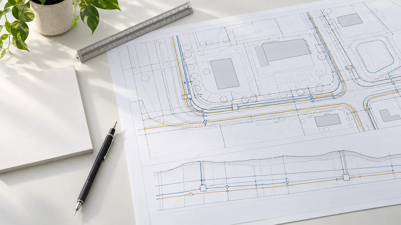
Plan and profile coordination concept. Municipal and infrastructure-owner requirements apply to each project.
Utility crossings in site servicing plans show how proposed water, sanitary and storm services pass above, below or beside other buried infrastructure. In Ontario, the design needs reliable location information, clear profiles and the applicable municipal and utility-owner criteria. A coordinated crossing detail makes the available space, remaining uncertainties and required reviews understandable before construction decisions are made.
Key Takeaways
- Check crossings in three dimensions, including the full outside dimensions of pipes, ducts and structures.
- Identify where existing utility information comes from and which elevations still need verification.
- Use the current criteria for the actual municipality, infrastructure owner and proposed work.
- Coordinate service profiles with building connections, grading, structures and maintenance access.
- Keep engineering review, utility-owner acceptance, construction permissions and excavation locates distinct.
The most useful crossing review happens while routes and building connections can still change. It should produce clear decisions, rather than a crowded drawing with unresolved notes passed on to the next project stage.
What Is a Utility Crossing in a Site Servicing Plan?
A utility crossing occurs where one service passes across another service’s route. A sanitary connection may cross a watermain near the street. A storm connection may pass below electrical ducts. A proposed water service may intersect a telecommunications corridor before entering the building.
The crossing point is only part of the design. The engineer also considers the approach on each side, the pipe or duct envelope, nearby fittings and the space needed to protect existing infrastructure. A pipe can clear another pipe while its connection fitting conflicts with a chamber wall.
Plans communicate the horizontal arrangement from above. Profiles show elevations along a route. Cross-sections explain a particular slice through the site. Together, they help the reviewer understand whether the proposed services can occupy the available underground space.
This article addresses that geometric coordination. Water demand, fire-flow availability and sewer capacity may require related analysis, but a capacity calculation does not resolve a physical conflict. Equally, a clear crossing does not establish that the receiving system can serve the development.
Toronto’s Site Servicing Plan terms of reference identify cross-sections showing vertical clearance from crossing sewers, watermains and other utilities. They also call for horizontal clearances and connection information. Those are Toronto application requirements, not a universal checklist for every Ontario property. City of Toronto site servicing requirements.
Start Utility Crossing Coordination with Reliable Records
Begin by bringing the project information onto a consistent base. The survey, architectural plan and servicing drawings should refer to the same property configuration and current building proposal. Identify the survey date and the source of each utility record before treating the combined drawing as dependable.
An old service drawing can help locate a possible connection. It may not establish its current depth, material, operating status or exact alignment. A line copied between drawing sets can acquire an appearance of certainty without acquiring better evidence.
Ask what is known at each important crossing. Is the utility position based on a historical drawing, a visible surface feature, a geophysical investigation or an exposed and measured point? Record the distinction in a way that remains visible when drawings are revised.
Toronto’s July 2026 design manual discusses subsurface utility engineering and references ASCE 38-22. Its quality levels distinguish records, surveyed surface features, geophysical information and exposed measurements. The highest level described establishes a utility’s position at a specific investigated point, not automatically along its entire route. Toronto Design Criteria, Chapter 1.
Track the Source and Status of Each Utility
Maintain the original source alongside the combined drawing. If two records disagree, preserve both and identify the discrepancy rather than quietly choosing the more convenient location. A useful record note states who supplied the information, when it was obtained and what part of the proposed route it covers. This makes a later design change easier to trace.
Also separate infrastructure status from location. An apparently abandoned line may still need owner confirmation and a defined treatment. Similarly, a visible chamber may connect to infrastructure whose route is unclear. These questions belong in the information review, before the project assumes that an unused service corridor is available.
For an owner, the practical question is straightforward: which unknown could change the design? A crossing near a fixed sewer outlet may deserve attention before a distant utility that does not constrain the proposed route. This helps focus the investigation on consequential decisions.
Utility Crossings: Design Information Versus Excavation Locates
Utility planning information supports route selection and design coordination. Excavation locates support the safe execution of a defined digging activity. The project needs the appropriate information at each stage; receiving one does not automatically complete the other.
The published Ontario One Call rules describe Design and Planning as an optional information service. Participating infrastructure owners provide location information rather than physical locates through that request. Check the current process through Ontario Dig Authority when planning the investigation and subsequent work. Ontario One Call rules, Design and Planning definition.
Private infrastructure deserves separate attention. Ontario Dig Authority explains that its public locate process does not include every privately owned buried service. Owners must arrange private locates where applicable, such as for certain electrical connections, private gas lines or sewer and septic infrastructure. Ontario Dig Authority public and private locates.
A design team should therefore identify both the known utility owners and potential private systems. An empty space on a municipal record should not be labelled clear solely because no utility line appears there.
If further field investigation is required, qualified parties need to arrange it with the relevant permissions and safety measures. Owners should not excavate to confirm a depth themselves. The engineering assignment should state who obtains investigation information, who interprets it and which design decisions remain dependent on it.
Read Utility Crossings Across the Plan, Profile and Detail
A plan should make it easy to trace each proposed service from its starting point to its intended connection. Crossing identifiers help a reader move from the overall layout to the corresponding profile or detail without guessing which intersection is being discussed.
A profile is particularly useful where a gravity sewer has limited elevation available. It shows how the proposed pipe falls along its route and where that route meets existing services. The profile needs enough length to explain the solution, rather than showing only a small gap at the conflict.
Use explicit elevation labels. The invert normally refers to the inside bottom of a pipe. A centreline elevation describes its middle, while an outside-top elevation describes its external upper surface. These are different reference points. The drawing should clarify the intended measurement instead of leaving the reader to infer it from a symbol.
Pay attention to profile scales. A drawing may deliberately use different horizontal and vertical scales to make elevation changes legible. Its apparent angle or slope should not be judged visually without reading those scales. Use the labelled values and design information, rather than measuring a screenshot or relying on how steep the line looks.
Tie Crossing Details to the Current Alignment
Stationing, sometimes called chainage, identifies distance along the selected route. When an alignment changes, a crossing can occur at a different station and therefore a different proposed elevation. Keep the profile tied to the current alignment. Reusing the earlier crossing elevation after a horizontal route change can hide a new conflict.
A crossing detail can then identify the upper and lower infrastructure, their external envelopes and the resulting clear distance. Where a duct bank or chamber is involved, represent the structure that occupies the space, not just the cables or pipe running through it.
For a useful drawing review, check the following together:
- Matching crossing identifiers on the plan and profile.
- Existing and proposed services shown with distinct linework.
- Elevation references, units and source information.
- External pipe or structure dimensions at the conflict.
- The applicable separation criterion and unresolved verification notes.
A neatly dimensioned detail can still be misleading when it uses an assumed utility depth. The evidence behind the dimensions is as important as the dimensions themselves.
Vertical Utility Crossings: Elevations Before Clearances
Vertical coordination begins with compatible elevation information. Two elevations cannot be compared reliably until the team confirms they use the same datum and reference system. A building drawing may use a project level, while a survey uses geodetic elevations. The relationship needs to be documented before those values appear in one profile.
Next, establish the actual surfaces being compared. Subtracting two pipe inverts gives a difference between internal bottoms. It does not give the open space between the pipes. Pipe size, wall thickness and any surrounding structure affect that space.
Cover is another separate measurement. It describes the relationship between buried infrastructure and the ground surface or another specified reference. Increasing clearance below a crossing by lowering a pipe may improve cover there but create a connection problem farther along the route.
Gravity services need a continuous review from the building to the receiving system. Lowering one section to avoid a conflict can make the downstream connection unworkable. Raising it can reduce cover or interfere with the building outlet. The engineer must assess the complete route and relevant hydraulic design.
Allow for Measurement Reliability and Nearby Constraints
Precision on the page also needs perspective. An elevation displayed to three decimal places does not necessarily come from a measurement accurate to one millimetre. The engineer should consider the reliability of the source, the conditions of measurement and reasonable construction allowances. A solution with virtually no practical room may need reconsideration even when its rounded dimensions appear to meet a minimum.
Check whether the tightest location is actually at the labelled crossing. Adjacent bends, changes in grade or the edge of a chamber can create a smaller gap nearby. Where infrastructure is wide or the crossing is angled, reviewing just one centreline intersection may miss the controlling condition.
Where the available information is uncertain, show that uncertainty explicitly. A proposed elevation should not be presented as fixed while a controlling existing utility remains unverified. Identify the investigation or owner response needed before the design can advance.
Horizontal Utility Crossings: Look Beyond Pipe Centrelines
Horizontal separation concerns the space beside infrastructure. A plan may show well-separated centrelines while the outside walls of a large chamber, duct bank or pipe remain too close. Evaluate the full physical dimensions and the particular measurement convention used by the governing criterion.
Crossing angle also matters. An oblique crossing keeps two services close together for a longer distance than a more direct intersection. The approach route may introduce additional fittings or move the service closer to a building, tree or property boundary.
Include access needs in the review. Maintenance holes, valves and equipment chambers need usable access after landscaping and paving are complete. Locating a service underneath an access structure can create a future problem even when the initial pipe arrangement appears possible.
Rights-of-way and easements introduce another boundary. A route that fits physically may extend beyond the area available for that service. The project team should confirm property information and obtain the appropriate property or legal input where rights are unclear.
Surface design also occupies space. Tree locations, proposed retaining walls, foundations, signs and loading areas can affect the preferred alignment. Coordinate those features before the underground layout becomes difficult to change, and revisit the review when another discipline moves them.
Which Ontario Utility Separation Requirements Apply?
There is no single clearance that can be copied onto every utility crossing. The correct requirement depends on the infrastructure types, owner, jurisdiction, arrangement and proposed installation. A watermain crossing a sanitary sewer raises different considerations from telecommunications ducts beside a municipal chamber.
Ontario’s drinking-water design guidelines discuss separation between watermains and sewers, including a recommended 0.5-metre outside-to-outside vertical distance at crossings. Their context is drinking-water system design. That value should not be presented as a universal rule for gas, electrical, telecommunications or every private building service. Ontario drinking-water design guidelines, Section 10.11.
Ontario Procedure F-6-1 separately addresses sewer and watermain arrangements, including parallel installations and watermains passing below sewers. Its provisions include protection and support considerations, so reducing the topic to one distance loses important context. Ontario Procedure F-6-1.
For Toronto work, consult the current municipal publications as well. The City’s standards index lists the third edition of its sewer and watermain design manual, dated July 1, 2026. Older search results may still lead to the 2021 edition. Toronto infrastructure standards.
Toronto’s September 2026 Municipal Consent Appendix O distinguishes infrastructure types and includes clearance conditions and owner permissions. It should be read within its municipal-consent context, rather than used to replace watermain-and-sewer criteria or project-specific requirements. Toronto Appendix O: cover and clearances.
Where requirements overlap or appear inconsistent, identify the issue for the relevant reviewers. The design should record the accepted approach and any conditions. An exception needs an engineering basis and the applicable review, not a copied note that says reduced clearance is acceptable.
Resolve Utility Crossing Conflicts in a Deliberate Order
First establish whether the conflict is real, apparent or still uncertain. A modelled collision caused by inconsistent elevation references calls for different action from a confirmed clash between two measured structures. Improving the information may change which design options deserve consideration.
Next identify the fixed constraints. These may include the accepted connection location, an existing trunk service, the building outlet or a boundary that cannot move. Compare those with elements that can reasonably be adjusted within the project scope.
A horizontal route change may avoid the congested area. However, it can increase the service length, require different fittings or encounter another obstruction. Review the whole altered route, including its connection points and surrounding features.
A vertical adjustment requires the same discipline. Recheck cover, gravity flow, building interfaces and structural conditions. Do not assume a water service can simply dip beneath another utility without considering its design requirements and the infrastructure owner’s expectations.
Relocation or specialized protection may warrant discussion when ordinary alignment changes are insufficient. The owner of the affected utility needs to be involved. A civil drawing should not direct a third-party utility relocation as though the project team controls that asset.
Keep a short decision record for each significant crossing: the identified issue, information relied upon, options considered, selected response and outstanding conditions. This gives later reviewers a way to understand the decision without repeating the entire investigation.
Utility Crossing Coordination: Follow Through on Responses
A coordinated drawing set relies on more than distributing a PDF. Each affected party should understand the proposed work, the specific conflict and the response being requested. A broad request to review everything can make a critical crossing harder to identify.
Use a crossing register where several interfaces need attention. It can record the service pair, location, information source, applicable criterion, responsible reviewer and current status. The register need not be elaborate; its purpose is to prevent an unresolved item from disappearing between drawing revisions.
Distinguish a request for records from a request for acceptance. Receiving utility mapping establishes a source of information. It does not show that the owner reviewed the proposed crossing, agreed to relocation or accepted a particular protection detail.
Municipal processes illustrate the importance of those distinctions. Richmond Hill’s municipal-consent guidance calls for proof of design circulation to affected utilities and identifies separate road-occupancy requirements. It also requires road-crossing sections that show depth and clearances. These requirements apply within that City’s stated process. Richmond Hill municipal-consent applications.
For subdivision coordination, Markham’s composite utility plan criteria describe utility review and signature information. That is another reason to establish the actual application pathway rather than assume all municipalities use the same circulation sequence. Markham composite utility plan criteria, Section G.
Make Each Review Request Specific
Make each request answerable. Provide a marked plan excerpt, the crossing identifier, the relevant profile and the proposed treatment. Explain whether the question concerns record accuracy, a required separation, asset protection or a potential relocation. This gives the receiving party a focused issue to assess instead of asking it to infer the decision from an entire drawing set.
Assign responsibility for follow-through. One team member should know which response is outstanding and which design decision depends on it. A status such as records received, crossing under review or accepted subject to conditions is more informative than simply marking every contacted utility as coordinated.
When comments arrive, record what changed and circulate the affected revision. A response to an earlier alignment may no longer apply after the route moves. Keep the approved or accepted scope identifiable, together with any conditions still requiring action.
Keep Utility Crossing Submissions and Construction Scope Aligned
A useful submission allows a reviewer to follow the crossing decision without searching through unrelated files. Provide the relevant plan, profile or section, supporting records and clearly identified outstanding items. The level of detail should suit the application stage and consequences of the crossing.
Check the package for consistency before issue. A revised pipe diameter on the plan should also appear in the profile. A moved maintenance hole should have matching coordinates, elevations and references. A new ground level should trigger a cover check instead of remaining isolated on the grading sheet.
The building interface deserves its own check. Confirm the service entry or outlet location with the responsible building-services designer. Wall penetrations, footings and below-grade structures can constrain the final approach, even if the street crossing is straightforward.
Application acceptance and construction authorization remain separate questions. Toronto directs approved utilities and non-utility applicants through different cut-permit processes, and warns that a cut permit does not remove other required approvals. Select the applicable process for the actual work and applicant. Toronto utility-cut permit guidance.
Define Construction-Stage and Temporary-Work Responsibilities
Construction-stage engineering services should be defined in the professional assignment. They may include reviewing reported discrepancies or preparing revised details within scope. The contractor remains responsible for its construction activities, and specialist investigations or utility-owner work need their own arrangements.
Temporary arrangements need attention when they affect the crossing. An existing service may have to remain operational while a replacement route is developed. The final drawing alone may not explain that transition. Identify any need for separate staging, temporary support or service-interruption planning, and confirm who is responsible for designing and reviewing those arrangements.
The same applies to future maintenance. A crossing that is physically possible today can be difficult to repair if access depends on removing another active service. Discuss that constraint during design rather than assuming a construction solution resolves the long-term interface. Permanent layouts and temporary work should have clearly defined review responsibilities.
If field conditions differ from the design basis, the affected work requires an appropriate response before proceeding on an improvised route. Communicate the location, measured information and drawing reference so the engineer and relevant infrastructure owner can assess the implications.
How Elmid Design Inc. Supports Utility Crossings in Site Servicing Plans
Elmid Design Inc. prepares site servicing plans for proposed water, sanitary and storm connections. For projects with utility crossing constraints, the engineering scope can include coordinated service layouts, relevant plan-and-profile drawings or crossing sections, elevation review and drawing revisions addressing identified conflicts. These deliverables should be defined against the site conditions, available investigation results and municipal submission requirements. Site servicing design services.
The starting point is the proposed development and its known constraints. Share the current survey, building plans, municipal comments and utility information. If a critical depth remains unknown, the proposal can identify the information needed before a detailed crossing solution is developed.
Coordination may involve the architect, mechanical designer, surveyor, utility owners and other specialists. Their responsibilities should remain clear. Elmid Design Inc.’s role is engineering and design consulting, not excavation, utility locating or pipe installation.
A good scope also explains the intended submission stage. An early feasibility review can identify constrained routes and investigation needs. Detailed design develops the selected arrangement into coordinated drawings. Municipal responses and later construction-stage questions may require additional work, depending on the agreed assignment.
Illustrative Coordination Example: A Constrained Frontage
Consider a conceptual redevelopment where a proposed gravity sanitary connection crosses an existing duct bank near the frontage. The building outlet and intended municipal connection limit the available fall. A water service and a proposed landscape feature also occupy the same general corridor.
At first, the plan shows no obvious problem because the proposed pipe is represented by a thin line. Reviewing the section reveals that its external top may be close to the underside of the duct bank. The team identifies the duct-bank depth as a controlling uncertainty.
For illustration, assume verified information later places the underside of the duct bank at elevation 100.35 metres. The proposed pipe’s outside top at the crossing is 99.95 metres on the same datum. The calculated clear gap is 0.40 metres. Those assumed values explain the geometry only; they do not establish an acceptable separation for any actual project.
The engineer compares that result with the applicable criteria and confirms the full duct-bank envelope. The review also checks the pipe approach, downstream connection and nearby services. A compliant gap at one point would not by itself resolve the entire route.
Compare the Alternative Route in This Illustration
Suppose an alternative alignment appears possible beside the original corridor. Before selecting it, the team checks the added pipe length, resulting elevations, landscape conflict and property limits. The affected utility owner receives the relevant arrangement for the required review.
The decision should also reach the other drawings. If the alternative route changes where the service enters the property, the grading and landscape teams need that information. If it changes the building connection, the building-services designer must review the interface. Otherwise, the coordinated civil section may conflict with a still-current drawing from another discipline.
Before issue, the team checks that the original unresolved crossing has been removed or clearly superseded. The revised drawing identifies which investigation results informed the change and which conditions still apply. That closes the immediate coordination loop without suggesting that one drawing settles every permission, construction method or future site condition.
The resulting deliverable is a coordinated plan and crossing section with clear references, design assumptions and review conditions. This example illustrates the value of resolving the controlling geometry before treating the servicing layout as settled.
Prepare Utility Crossing Information for Engineering Review
Owners can improve the first discussion by sending one current project package instead of isolated screenshots. Include the latest proposed building layout and identify known changes since any earlier servicing design. Explain whether the immediate goal is feasibility, an application response or detailed coordination.
Useful starting information includes:
- The property address and a concise description of the proposed work.
- Available boundary and topographic survey information.
- Current architectural, grading and servicing drawings.
- Municipal comments and known submission requirements.
- Utility records, investigation reports and relevant owner correspondence.
- Known easements, existing connections and proposed construction phases.
Identify missing items honestly. It is better to flag an unavailable utility depth than to insert an assumed value without a visible qualification. The engineer can then explain whether the gap blocks design or can be managed through a defined next step.
Ask for a scope that distinguishes engineering fees from surveys, field investigations, utility-owner charges and construction costs. These depend on the project. A simple crossing and a congested frontage with several asset owners should not be assumed to need the same effort or review schedule.
Frequently Asked Questions
Do all utility crossings need a profile?
The required drawings depend on the municipality, application and complexity. A profile or crossing section is particularly useful when elevations control the design. Toronto’s Site Servicing Plan requirements expressly include service cross-sections showing crossing clearances. Confirm what the reviewing authority expects for the actual proposal. Toronto application terms of reference.
Can an existing utility drawing confirm the crossing depth?
Only to the extent supported by its source and reliability. A record drawing may provide useful background without proving the present elevation at the proposed crossing. Where depth controls the solution, the engineer should identify the investigation needed and distinguish a measured point from an assumed continuation.
Is 300 millimetres enough separation between utilities?
There is no blanket answer. Requirements vary with the services, infrastructure owners and crossing conditions. Do not apply a familiar dimension to another service pair without checking the relevant criterion, its measurement points and any additional protection or review requirements.
Can the engineer move an existing gas line or electrical duct?
A proposed relocation requires coordination with the infrastructure owner. Showing it on a civil drawing does not grant permission to alter the asset or establish who will design and execute that work. The project team should confirm ownership, review requirements, responsibilities and any programme implications before relying on relocation.
Does a servicing-plan review replace utility locates?
No. Excavation requires the applicable locate process and complete responses for the planned work. Ontario Dig Authority instructs excavators to wait for all notified infrastructure owners to respond and to follow the complete locate package. Private services may require separate arrangements. Ontario Dig Authority locate guidance.
What if a crossing changes after the drawings are issued?
Refer the change to the responsible engineer and affected infrastructure owner before relying on the revised arrangement. A small shift can alter another clearance, connection elevation or review condition. Track the revision across the plan, profile and related documents so the project team works from consistent information.
Geographic Locations That We Service:
Explore our Ontario service areas
Our Licensed Professional Engineers prepare site servicing plans and coordinate proposed utility crossings for residential, commercial and land development projects in Ontario. Applicable criteria depend on the municipality, infrastructure owner and agreed project scope. Related site coordination can include site grading plans and erosion and sediment control plans.
We provide engineering services across a wide range of municipalities, each with its own requirements and review processes.
Toronto and Surrounding Areas
We provide engineering services in Toronto and provide grading engineering resources through our Toronto grading plan page.
Our service area also includes Oshawa, Pickering with our Pickering grading plan resources, and Clarington.
We also provide engineering services in Ajax through our Ajax grading plan resources, Whitby, Brock, Scugog, and Uxbridge, including our Uxbridge grading plan resources.
Halton Region
Within Halton Region, we provide engineering services in Burlington, including projects requiring Burlington grading plans.
We also provide engineering services in Halton Hills, supported by our Halton Hills grading plan resources.
Our service area also includes Milton and Oakville, including our Oakville grading plan resources.
Peel Region
Within Peel Region, we provide engineering services in Brampton, including projects requiring Brampton grading plans.
We also provide engineering services in Mississauga through our Mississauga grading plan resources and Caledon through our Caledon grading plan resources.
York Region
Within York Region, we provide engineering services in Vaughan and provide information about Vaughan grading plans.
We also provide engineering services in Aurora through our Aurora grading plan resources and East Gwillimbury through our East Gwillimbury grading plan resources.
Additional service areas include Georgina with our Georgina grading plan resources, Markham with our Markham grading plan resources, and Newmarket with our Newmarket grading plan resources.
We also provide engineering services in Richmond Hill with our Richmond Hill grading plan resources, Whitchurch-Stouffville through our Whitchurch-Stouffville grading plan resources, and King through our King grading plan resources.
Our service area also includes Bradford West Gwillimbury.
Other Southern Ontario Cities and Towns
We provide engineering services in many additional Southern Ontario communities, including Hamilton, St. Catharines, Niagara-on-the-Lake, Brant, Cambridge, Kitchener, Waterloo, and Woodstock.
We also provide engineering services in Guelph, Centre Wellington, Shelburne, Orangeville, New Tecumseth, Essa, Collingwood, Wasaga Beach, and Barrie, including our Barrie grading plan resources.
Additional service areas include Midland, Orillia with our Orillia grading plan resources, Ramara, Minden Hills, North Kawartha, Kawartha Lakes, Peterborough, Selwyn, and Brighton.