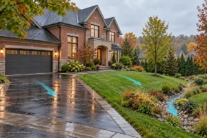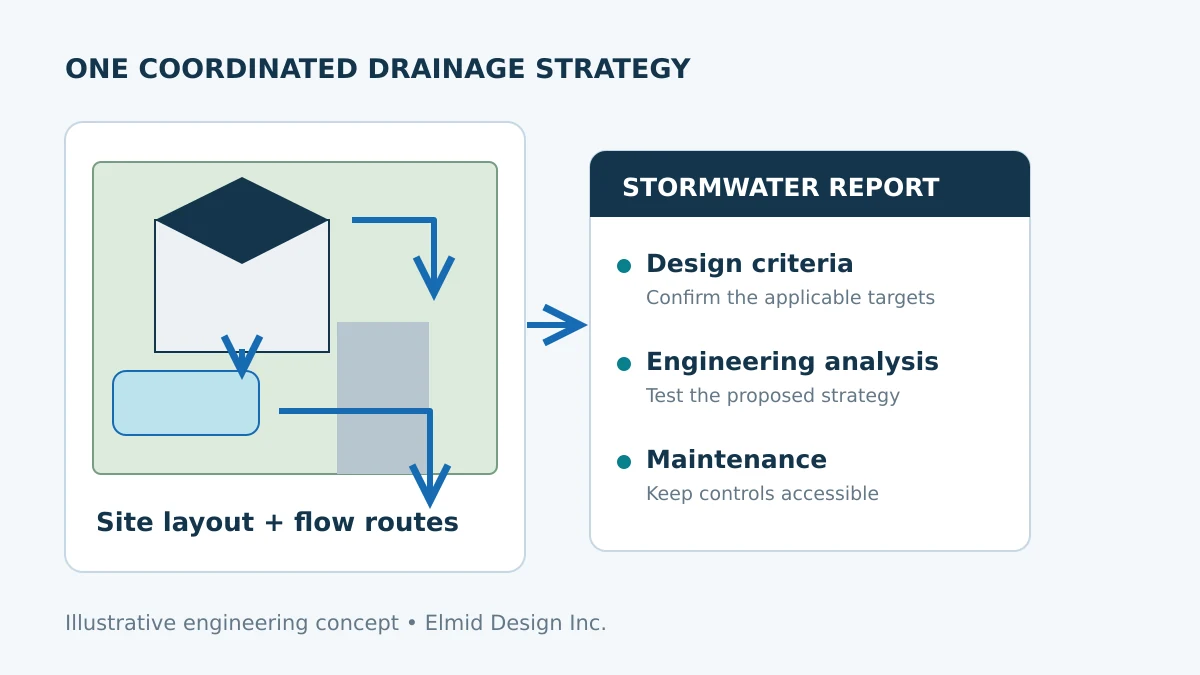
Illustrative stormwater management plan example showing how the drawing and report form one coordinated drainage strategy.
A stormwater management plan example shows how a development’s drainage drawings, runoff calculations and proposed controls fit together. This Ontario guide walks through an illustrative residential redevelopment, explains what each part demonstrates, and helps owners understand the information an engineer needs for a site-specific submission.
Key Takeaways
A useful stormwater management plan example explains both the design logic and the drawing symbols. Keep these points in mind when reviewing any sample:
- The plan connects existing drainage, proposed development, design criteria, calculations and maintenance.
- A drawing alone does not establish that a stormwater system meets the applicable criteria.
- Municipal requirements and site conditions determine the scope. An example’s dimensions or storage volume cannot simply transfer to another property.
- Grading, servicing and landscape designs must agree with the stormwater strategy.
What Does a Stormwater Management Plan Show?
A stormwater management plan explains where runoff comes from, how it moves through a site, and how the proposed development will manage it. Depending on the assignment, the submission may include a report, drawings, calculations, modelling files and maintenance instructions.
The word “plan” can mean the overall drainage strategy or a particular drawing sheet. Therefore, ask which deliverable the municipality requires. For example, a short drainage brief and a detailed stormwater report serve different levels of review.
Ontario’s Stormwater Management Planning and Design Manual describes an integrated approach to protecting water balance, water quality, watercourses and flood conditions. The 2003 manual provides provincial technical guidance. The engineer must also confirm current municipal criteria, applicable approvals and site-specific conditions.
For example, Toronto’s application-support terms of reference describe a stormwater report supported by appropriate plans, modelling and calculations. That is a Toronto submission requirement where applicable, rather than a universal checklist for every Ontario house.
Stormwater Management Plan Example: The Illustrative Site
Consider a fictional 800-square-metre property with an existing house, driveway, patio and lawn. The owner proposes a larger house footprint and additional hard surfaces. This teaching example illustrates how an engineer organizes the review; it is not an Elmid Design Inc. project or a municipal submission template.
The first task is to establish existing conditions from reliable survey information. The engineer checks the property boundaries, ground elevations, buildings, neighbouring grades and drainage features. The team also identifies the receiving drainage system and confirms whether it can serve the proposal.
For this stormwater management plan example, assume the initial review identifies a potential municipal storm connection. Its acceptability and available capacity remain matters for investigation and municipal review. The example does not assume that a nearby pipe automatically provides an approved outlet.
Surface-Area Schedule for the Example Plan
The following arithmetic describes the fictional proposal only. These areas are not design limits or approval thresholds.
| Surface | Existing area | Proposed area |
|---|---|---|
| Roof footprint | 160 m² | 220 m² |
| Driveway | 60 m² | 80 m² |
| Patio | 20 m² | 40 m² |
| Lawn and planted area | 560 m² | 460 m² |
| Total property | 800 m² | 800 m² |
The combined roof, driveway and patio area increases from 240 to 340 m². That changes the illustrative hard-surface share from 30% to 42.5%, an increase of 100 m². However, these percentages alone do not determine a tank size, allowable discharge or infiltration design.
The drainage analysis must also account for where these surfaces drain. For example, one roof area may reach a different outlet from another. Runoff from beyond the property may also enter the site, so the study boundary may extend beyond the legal boundary.
Stormwater Plan Example: Four Development Conditions
A useful stormwater management plan example clearly separates the conditions being compared. “Before” and “after” can otherwise hide an important difference between the surveyed property and the baseline required for design.
Existing Conditions in the Stormwater Plan
The existing-condition plan records the current buildings, surfaces, grades and drainage routes. In our illustration, those surfaces include 240 m² of roof, driveway and patio. Similarly, survey records and site observations should support the real project’s corresponding schedule.
Also record drainage from neighbouring land and features outside the property that affect the outlet. Otherwise, the analysis may describe the owner’s lot accurately while missing water that arrives from elsewhere.
The Stormwater Plan’s Pre-Development Baseline
The pre-development baseline is the reference condition used to assess the proposal. It may match the existing site, but the applicable criteria can require different assumptions. Therefore, the engineer must identify the baseline and its source before calculating allowable performance.
For this fictional property, the report would state whether the 240 m² existing hard-surface area belongs in that baseline. It would also explain any different prescribed land-cover assumptions. Therefore, stating the required baseline clearly lets the reviewer trace the comparison.
Stormwater Plan Example Without Controls
The uncontrolled post-development scenario represents the proposed layout before accounting for the intended stormwater measures. Here, the hard-surface area becomes 340 m². As a result, this scenario helps explain the proposal’s effect and the need for the selected controls.
However, area alone is not the full comparison. Revised slopes, downspout connections and drainage boundaries can change runoff routes and timing. A small area change beside a low entrance may deserve close attention.
Stormwater Plan Example With Controls
The controlled post-development scenario includes the proposed drainage measures. The engineer assesses the relevant results against the required criteria and checks whether the drawings implement those assumptions.
A clear results summary labels each scenario rather than presenting two unexplained columns of numbers. For applicable development submissions, York Region’s June 2024 stormwater-report terms of reference expressly identify pre-development and post-development conditions, drainage catchments, external contributing areas and design assumptions. This supports the comparison approach without making that regional checklist universal.
How to Read This Stormwater Plan Example
The annotated stormwater management plan example below separates six items that should connect across a real submission. It intentionally omits construction dimensions and design elevations. The final arrangement would depend on the survey, calculations and accepted drainage strategy.
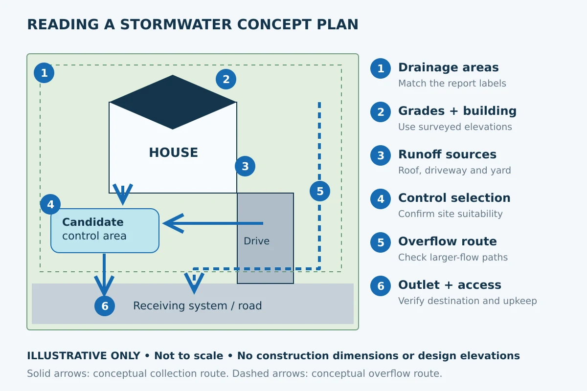
1. Drainage Areas and Boundaries
A drainage area is the land that contributes runoff to a chosen point. For clarity, drawing labels should match the calculation labels. If the report refers to Area A, the reviewer should find Area A on the plan without guessing.
For the fictional site, the engineer might separate roof drainage from driveway runoff and landscaped areas. This helps explain which surfaces reach each proposed control and which flows follow another route.
2. Grades, Swales and Building Levels
Existing and proposed elevations show how water moves. Swales are shallow surface channels that guide runoff. Floor levels, entrances and low points help the engineer assess whether proposed flow routes could affect the building.
A site grading plan supplies this physical framework. If a later architectural revision changes a walkout or driveway, the drainage design may also need revision.
3. Roof and Paved-Surface Drainage
The drawing should identify downspout locations and the intended destinations for collected runoff. It should also show how driveway and patio runoff enters the drainage system. Therefore, those connections must agree with the areas used in the calculations.
In addition, separating sources makes the design easier to assess. Roof runoff and runoff from vehicle-use areas can present different treatment considerations. Therefore, the engineer evaluates their suitability for the proposed controls.
4. Candidate Stormwater Controls
In this example, a labelled control area reserves space for a measure that the engineering analysis will select. Options may involve storage, controlled release, infiltration or a combination. The drawing does not presume that any one device suits the property.
Infiltration needs an assessment of soils, groundwater, available space and nearby features. If it is unsuitable, the engineer must consider other feasible strategies with the reviewing authority. A convenient empty corner is not enough evidence for a design.
5. Overflow and Larger-Storm Routes
The plan should explain what happens when runoff exceeds a control’s operating capacity or an inlet becomes obstructed. This includes the surface route, affected low points and connection to the broader drainage system.
Show the ordinary collection route and the overland route clearly. Arrows need supporting elevations and capacity checks in a real design. However, a drawn arrow by itself does not establish safe drainage.
6. Outlet and Maintenance Access
The proposed outlet needs a defined destination, elevation and basis for acceptance. A pipe crossing a boundary may also raise access or property-right questions. Therefore, those issues should be resolved through the appropriate review.
Finally, show how the owner or maintenance provider will reach components that require inspection or cleaning. A control beneath an inaccessible structure can create a long-term maintenance problem even when it appears to fit on a drawing.
Runoff Calculations in a Stormwater Management Plan Example
Owners sometimes see a storage result without the assumptions behind it. A useful stormwater management plan example makes that connection clear. This is particularly important when comparing design options or deciding whether a later site change needs reassessment.
Rainfall, Duration and the Question Being Answered
The engineer identifies the rainfall information and assessment conditions accepted for the project. A short, intense event and a longer event can challenge different parts of a drainage system. Therefore, the report should explain the selected analysis rather than referring vaguely to “a major storm.”
Also distinguish peak flow from runoff volume. Peak flow describes how quickly water passes a point at the busiest moment. Volume describes how much water passes over the event or assessment period. However, managing one does not automatically demonstrate the other.
Ontario’s introduction to stormwater planning and design explains the broader water balance: development can alter runoff, infiltration and transfers back to the atmosphere. An owner can use that distinction to ask whether a proposed control addresses discharge timing, water volume or both.
Surface Types and Travel Times
The model needs information about drainage areas, surface types and how runoff reaches the assessment point. A roof connected directly to a pipe behaves differently from a surface routed through a suitable landscaped area. Those routes must therefore match the drawings.
Time of concentration estimates how long runoff from the hydraulically most distant part of a drainage area takes to reach the selected outlet. Its selection is an engineering input, not a number to copy from another report. For this reason, the report should make the method and relevant flow path traceable.
For the fictional site, the same 800 m² boundary could support several drainage arrangements. Consequently, the area schedule remains useful but cannot replace the drainage-area plan and the assumptions behind it.
Soil Tests and Design Infiltration Rates
A measured infiltration result is evidence, but it is not automatically the rate used in design. The test method, location, depth and site variability all matter. Therefore, the engineer must explain how the available evidence supports the selected design assumption.
The Sustainable Technologies Evaluation Program’s design-infiltration guidance distinguishes design rates from raw soil measurements and addresses conservative adjustments. For an actual property, ask whether testing represents the proposed feature’s location and depth, and what limitations remain.
Likewise, a dry-looking test location does not establish seasonal groundwater conditions. If groundwater, soil variability or nearby foundations constrain the design, the report should identify the information needed to resolve those constraints.
Example Stormwater Management Report Structure
A well-organized report lets the reviewer follow the same design decisions as the engineer. For this stormwater management plan example, the following structure provides a practical reading guide. The municipality may request additional sections or a different submission format.
Project Description and Existing Conditions
Start with the property, proposed work and purpose of the submission. Identify the survey and drawing revisions used. Then explain existing drainage routes, receiving infrastructure, relevant site constraints and any known drainage concerns.
For the fictional property, this section would document the existing 800 m² area schedule and the basis for the potential outlet. It would also identify information that remains outstanding, such as field testing or municipal infrastructure records.
Design Criteria and Analysis
List each applicable target, its source and the method used to assess it. Depending on the project, topics may include runoff quantity, water quality, erosion, water balance and overflow routing. Also keep municipal criteria separate from assumptions adopted for analysis.
The engineer then compares the required baseline and proposed conditions using suitable methods. A municipality may specify a pre-development baseline that differs from the lot’s current condition. Therefore, the illustrative existing-area schedule is not automatically the regulatory baseline. The calculations should be traceable to the plan’s drainage areas and surfaces. Explain assumptions, model inputs and any limitations that affect interpretation.
A results summary should distinguish required performance from calculated performance. For example, it can identify the applicable discharge criterion, the proposed release result and the drawing detail that implements it. This example supplies no numerical target because the municipality and outlet have not been selected.
Proposed Controls and Supporting Details
Explain why the selected approach fits the site and how its components work together. Include the details needed to review storage, inlets, outlets, treatment features and maintenance access. If the design relies on infiltration, identify the testing and assumptions supporting that reliance.
Also coordinate this information with the site servicing plan. Pipe routes, connection points and elevations should be consistent across the submission rather than left for interpretation during construction.
Construction-Stage Protection and Maintenance
Temporary sediment controls help protect drains, receiving waters and neighbouring land while soil is disturbed. Permanent controls manage runoff after the development is complete. The submission should explain the relationship between these stages, including protection of features that sediment could clog.
A separate erosion and sediment control plan may form part of the package. Maintenance information should identify the components, access arrangements, inspection tasks and circumstances that require corrective attention.
Choosing Controls for the Stormwater Plan
Begin with the performance questions, then consider the measures that can answer them. Otherwise, selecting equipment first can leave the team trying to fit the site to an unsuitable device.
Separate the Performance Objectives
Water-quantity assessment addresses runoff rates, levels and related flooding concerns. Water-quality assessment considers the runoff’s effect on receiving waters. Erosion assessment considers how changed flows may affect a watercourse. Water-balance assessment examines changes in the movement and storage of water.
These objectives are related, but they are not interchangeable. Ontario’s environmental design criteria guidance treats them as distinct parts of the assessment. For example, reducing a site’s discharge peak alone may not resolve downstream timing effects or the need to address water quality.
For our illustrative lot, the report would list the applicable objectives and identify the drawing or analysis addressing each one. Where an objective does not apply, the report should explain the basis rather than leave an unexplained omission.
Compare Feasible Site Arrangements
Suppose the first concept reserves part of the yard for infiltration. Testing and site constraints then determine whether that option remains feasible. If it does, the engineer can assess the required arrangement, overflow and maintenance access.
Alternatively, suppose the investigation identifies slow-draining soils or an unsuitable groundwater condition. The team may need to reassess the proposed hard surfaces, storage strategy, reuse options or accepted discharge arrangement. A different device name does not resolve the underlying site constraint.
STEP’s guidance on low-permeability soils discusses how limited infiltration can change the appropriate approach. It is a useful explanation of why a generic soakaway detail should not decide the design.
Keep the Building and Landscape Plans in the Decision
Next, check what the preferred approach needs from the other drawings. A downspout route may require space beside an entrance. A storage feature may need access through a landscaped area. An overflow path may limit where a raised patio can sit.
Therefore, resolve these interfaces while the layout can still change. This produces a more coherent submission than adding disconnected notes to several drawings near the end of design.
How Municipal Review Changes a Stormwater Plan Example
Start with the current submission requirements for the property. A plan prepared for one municipality may not answer another municipality’s questions. Existing watershed studies, servicing constraints and site-specific conditions can also affect the design.
For a concrete local example, Clarington’s site plan guidance identifies grading, drainage, servicing and erosion-control drawings among typical supporting plans. It lists details such as elevations, swales, roof-water discharge points and stormwater devices. Staff determine the required package for the proposal.
Similarly, Toronto’s terms of reference require the applicable stormwater report to be prepared by a licensed Professional Engineer with relevant specialization. Toronto also explains that the required studies and their level of detail depend on the application. Confirm scope before commissioning a full package.
Where another authority or approval process applies, identify it early. Do not assume that municipal acceptance resolves every separate permit, connection permission or property issue.
Residential Redevelopment and Infill Need Different Site Questions
A replacement home on an established street may face tight boundaries, mature trees and a fixed municipal drainage outlet. A larger infill proposal may involve several drainage catchments, new connections or staged works. Consequently, the number of buildings alone does not determine the engineering effort.
Ontario’s infill-development guidance recognizes the space and infrastructure constraints of developed areas. It also discusses cumulative effects from multiple projects. Use this technical context alongside current local requirements, rather than importing the chapter’s historic examples as current municipal policy.
For either proposal, identify which parts of the drainage system can change and which are fixed constraints. That distinction helps explain why two similarly sized properties may need different investigations and controls.
Owner’s Stormwater Management Plan Review Checklist
Owners do not need to reproduce the engineering calculations to spot coordination gaps. Before submission, ask the project team these questions:
- Do all drawings use the same current site layout and revision?
- Can each drainage area in the calculations be found on the plan?
- Are the proposed outlet and overflow route clearly explained?
- Do the report’s control sizes and elevations match the drawing details?
- Are investigation results and outstanding assumptions identified?
- Can the completed controls be inspected and maintained?
If the answers are unclear, resolve them before the package goes to review. A tidy drawing set helps, but the important issue is whether the documents describe one coordinated, supportable design.
Stormwater Plan Records for Construction and Maintenance
A report should remain understandable after design review. Therefore, the owner, construction team and reviewing professional need clear records of accepted documents, required observations and later changes.
Before Components Become Concealed
Before construction, ask which observations or records the engineering assignment requires. Some details can be difficult to verify after backfilling or final landscaping. Therefore, agree on notice, access and documentation while those details remain visible.
For example, the team may need records of actual feature locations, elevations or connections. Photographs can support that record, but they do not automatically establish every design condition. The reviewing professional should identify the evidence appropriate to the assignment.
If the field conditions differ from the drawings, raise the difference before improvising a change. A relocated inlet or revised pipe level can affect storage, flow routes or access. Keep the agreed revision with the project documents.
Maintenance as Part of the Design
Ask who is expected to inspect each component and how that person reaches it. An owner-friendly maintenance sheet should connect the drawing labels to the relevant tasks, warning signs and instructions.
For instance, accumulated sediment, recurring overflow or water remaining longer than the design anticipates can warrant assessment. The appropriate response depends on the actual system. Do not treat a generic inspection interval as a substitute for the project’s maintenance instructions.
Finally, keep a record of significant observations and servicing. This helps distinguish an isolated blockage from a recurring issue and gives a future engineer useful information when the property changes.
Using a Stormwater Plan Example to Define the Engineering Scope
A sample report can help you request a clearer engineering proposal. First, explain what decision the work must support. An early feasibility review, a permit submission and a detailed coordinated design may require different information and deliverables.
Next, confirm who will obtain the topographic survey and any necessary soil or groundwater information. Identify who supplies the current architectural layout and who coordinates revisions. If an existing report is available, ask whether it can support the new assignment or needs further assessment.
The proposal should describe the expected drawings, calculations and report, together with assumptions about available records. It should also explain the included review support. For example, responding to a clarification on the submitted design can differ from redesigning drainage after the owner changes the building footprint.
Also separate design preparation from external review and later construction-stage services. Ask whether the assignment includes site observations, completion records or maintenance information. Those services should be discussed before the owner relies on them.
Finally, identify the next milestone and the information needed to reach it. A clear sequence of survey review, layout coordination, design, submission and comment responses is more useful than a completion date that ignores missing information or third-party decisions.
Documented Project Examples at Different Scales
The fictional lot above explains how to read a plan. These separate project examples show how engineering scope changes with development scale. These examples concern documented design and review stages.
Clinton Drive Extension, Richmond Hill: subdivision coordination
Elmid Design Inc. prepared stormwater-management and civil engineering documents for the proposed seven-lot Clinton Drive Extension subdivision in Richmond Hill. The September 2020 stormwater report connected drainage-area analysis and runoff-storage calculations with lot grading and servicing design. It considered interim subdivision conditions and future drainage arrangements.
The design included controlled discharge, underground pipe storage, oil-grit separation and water-balance measures, including an infiltration trench. This example shows why road, lot and utility design must share a coordinated drainage strategy.
155 King Road, Richmond Hill: commercial design comparison
For the proposed commercial office development at 155 King Road, Elmid Design Inc. prepared stormwater and functional servicing reports, plus grading, site servicing and erosion-control plans. The documented 2023 scope addressed a proposed two-storey office building. The February report package was issued for review as a draft.
The stormwater strategy combined rooftop detention, underground storage, outlet controls, an oil-grit separator and a landscaped bioswale. Analysis considered pre-development and proposed runoff, water quality and water balance. This commercial example highlights the coordination between drainage, building design and municipal service connections.
228–232 Finch Avenue West, Toronto: higher-density residential coordination
Elmid Design Inc. provided stormwater engineering support for the proposed redevelopment at 228–232 Finch Avenue West in Toronto. The proposal comprised 36 townhouses and one level of underground parking. The project’s stormwater documentation addressed stormwater quantity, quality and water balance.
Underground storage, controlled discharge, runoff treatment and irrigation reuse were considered with grading and servicing constraints. Elmid Design Inc. coordinated technical responses and revised submission material with the project team. This example shows why drainage calculations must connect with building levels, overland flow routes and underground parking.
Stormwater Management Plan Support From Elmid Design Inc.
Elmid Design Inc. provides professional stormwater management, grading, drainage and site servicing engineering in Ontario. Depending on the assignment, services can include reviewing available site information, developing the drainage strategy, preparing calculations and drawings, and responding to technical review comments.
Elmid Design Inc. holds a Certificate of Authorization from Professional Engineers Ontario (PEO). The project scope is tailored to the property and the applicable review process.
To request an engineering proposal, share the property address, available survey, proposed site plan and municipal correspondence. Include any previous drainage reports and known site concerns. These records help define the investigations and design work needed.
Frequently Asked Questions
Can I Use This Stormwater Management Plan Example for a Permit?
No. This illustrative example is a reading aid for understanding a submission and discussing scope with your engineer. A permit submission needs information, criteria and professional design specific to the property. This illustrative layout has no surveyed elevations, calculated control sizes or municipal acceptance.
Is a Stormwater Plan the Same as a Grading Plan?
They serve related but different purposes. A grading plan establishes ground levels and surface drainage routes. A stormwater submission assesses runoff and the controls needed to meet applicable criteria. Some projects combine information on a coordinated drawing set; others need a separate report and supporting calculations.
Does More Hard Surface Always Mean a Storage Tank?
No single device follows automatically from the area increase. The engineer considers the drainage criteria, outlet, soils, groundwater and available space. A suitable design may use one measure or several coordinated measures, subject to the applicable review.
Why Are There No Universal Storm or Storage Numbers Here?
Those numbers must come from the applicable criteria and project analysis. Copying a rainfall depth, return period or storage volume from another site can create a misleading design. The fictional area schedule explains the comparison process without presenting assumptions as Ontario-wide requirements.
Can an Existing Report Be Reused After a Site-Plan Change?
The engineer should review the change first. A different footprint, driveway, roof layout, grade or outlet can alter the analysis. The revised drawings and report should describe the same proposal, with changes assessed and documented as needed.
What Makes a Stormwater Submission More Complex?
Complexity can increase when survey information is incomplete, outlet capacity is uncertain, groundwater limits options, or several review authorities are involved. Tight grading constraints and changes to the proposed layout can also add work. A proposal should identify assumptions, included investigations and revision scope.
What Should the Owner Keep After the Design Is Complete?
Keep the accepted drawings, final report, applicable approvals, construction records and maintenance instructions. Where the project requires inspection or completion documentation, retain those records too. They help future owners and designers understand the drainage system before making changes.
Geographic Locations That We Service:
Our Licensed Professional Engineers provide professional engineering and design services for stormwater management plans and reports, drainage design, coordinated site grading plans, and erosion and sediment control plans to support applicable site plan approval and building permit applications in Ontario.
We provide engineering services across a wide range of municipalities, each with its own requirements and review processes.
Toronto and Surrounding Areas
We provide engineering services in Toronto and provide grading engineering resources through our Toronto grading plan page.
Our service area also includes Oshawa, Pickering with our Pickering grading plan resources, and Clarington.
We also provide engineering services in Ajax through our Ajax grading plan resources, Whitby, Brock, Scugog, and Uxbridge, including our Uxbridge grading plan resources.
Halton Region
Within Halton Region, we provide engineering services in Burlington, including projects requiring Burlington grading plans.
We also provide engineering services in Halton Hills, supported by our Halton Hills grading plan resources.
Our service area also includes Milton and Oakville, including our Oakville grading plan resources.
Peel Region
Within Peel Region, we provide engineering services in Brampton, including projects requiring Brampton grading plans.
We also provide engineering services in Mississauga through our Mississauga grading plan resources and Caledon through our Caledon grading plan resources.
York Region
Within York Region, we provide engineering services in Vaughan and provide information about Vaughan grading plans.
We also provide engineering services in Aurora through our Aurora grading plan resources and East Gwillimbury through our East Gwillimbury grading plan resources.
Additional service areas include Georgina with our Georgina grading plan resources, Markham with our Markham grading plan resources, and Newmarket with our Newmarket grading plan resources.
We also provide engineering services in Richmond Hill with our Richmond Hill grading plan resources, Whitchurch-Stouffville through our Whitchurch-Stouffville grading plan resources, and King through our King grading plan resources.
Our service area also includes Bradford West Gwillimbury.
Other Southern Ontario Cities and Towns
We provide engineering services in many additional Southern Ontario communities, including Hamilton, St. Catharines, Niagara-on-the-Lake, Brant, Cambridge, Kitchener, Waterloo, and Woodstock.
We also provide engineering services in Guelph, Centre Wellington, Shelburne, Orangeville, New Tecumseth, Essa, Collingwood, Wasaga Beach, and Barrie, including our Barrie grading plan resources.
Additional service areas include Midland, Orillia with our Orillia grading plan resources, Ramara, Minden Hills, North Kawartha, Kawartha Lakes, Peterborough, Selwyn, and Brighton.